
How-to (new) - Fazer8 dual low beam mod - COMPLETE
Hi all,
When I mentioned I had done this mod a few days ago a number of people asked for a write-up on how I did it. I'll start with a basic how-to and add details & pics as I find time. Yamaha made this an easy mod by fitting the Fazer with a dual-filament bulb & reflector on the high beam side. They just didn't bother wiring in the additional low beam.
If you recall, another forumite (Fazed) also posted a how-to for this mod. He took a very direct approach, and a very simple one, but as I had noted in his thread I had concerns about the load on the factory wiring. He had said he was told the low beam wire he utilized for 12V power (running through the hi-lo beam switch) was not used in the Fazer8, but with no proof of that and a bit of a background in my hobby of building tube amplifiers I still felt there was a better, and safer, way to approach it. I also don't like running a lot of current through a switch if it is avoidable. So here we go.
I know that looks like a lot, but I'm a systems analyst by trade so detail is kinda my thing. This really isn't a difficult mod - just be careful & meticulous and you should be just fine. If you don't feel 100% comfortable doing this modification, get a professional or a competent friend to do it.
I don't claim this is the best way to do this, and certainly not the simplest, but I feel it's a safe approach that isolates the new circuit from the factory wiring.
First, the parts list. Where applicable, the part# I used is in parenthesis. I got all of the stuff at Canadian Tire.
- In-line fuse - weatherproof (Littelfuse FHAC2BP/FHAC0002XP)
- SPST automotive headlight relay (Pilot PL-RY2CT)
- 1 x .250" female spade connector (for right headlight plug, low beam filament)
- 4 x .250" female spade connector OR SPST relay socket (for connections to relay)
- 2 x 1/4" ring terminals (weatherproof) (battery/ground connections) (Motomaster 20-6982-8)
- approx 12' 16 AWG wire (your choice of colors - I had red & black on hand).
- 1 t-tap for 16AWG wire (or splice/solder if you prefer)
- 1 10A fuse (current draw is 5-6 amps)
- A few feet of 1/4" automotive wiring loom flex tubing. (Certified 020-7502-6)
Here's a wiring diagram for the circuit with the relay. Pretty straight forward really.
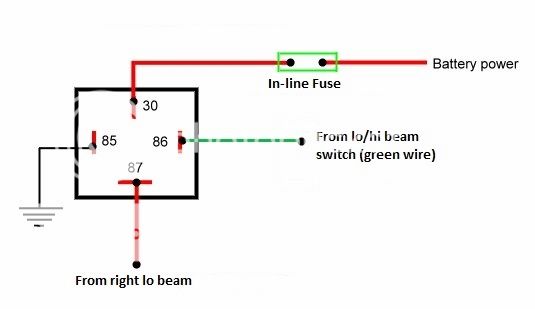
Some of you probably have the know-how to take things from there. When I get some time I'll post some more details & pics on how I implemented this. There are many ways to go about it. I took an approach where I didn't have to disassemble the whole freakin' bike and still kept things tidy.
*** PLEASE NOTE *** When I talk about the right side headlight in the descriptions below, I and referring to the right side when sitting on the bike. Facing the bike it is the LEFT headlight.
Here's how I did it...
Step 1: Add low beam wire to factory right headlight plug
- Unplug the right headlight plug
- Use a small screwdriver to release the back of the plug. You should see a vacant slot at the top of the plug. You will be inserting a .250" female spade connector in there...but not just yet!
- test fit your spade connector on the headlight bulb. It should be snug. .250" is a little too narrow really, and I had to open mine up a touch. If you can find the correct spade connector or have an old H4 connector kicking around that you can cannibalize that would be ideal. I had neither.
- Once you have your spade connector fitting the bulb, remove it and crimp or solder on a length of 16 AWG wire. Cut a 6' length for now. You can trim it to fit later. If your spade connector has a plastic cover, remove it.
- Insert the new wire into the vacant slot in the headlight plug. Route the wire at right angles to the plug in the available channel, and snap the back on the plug.
- Test-fit the plug to the headlight bulb. If everything fits OK, move on. If not, mess with the fit until you are comfortable with it.
- Tape the new wire to the last couple of inches of the factory wires/loom for the right headlight.
- Run the new wire along side the factory loom along the bottom edge of the cowling and around to the left side. Tape it & zip tie it to the original loom along the way where possible.
- Optional You could disassemble the upper cowl to get at the factory loom and tape the new wire in in the whole way along. Up to you. IMO it isn't worth the trouble. If the new wire is behind the cowl with the loom & secured it should not be a problem. It will be out of the weather & should be well protected.
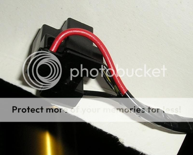
Here's a pic of the modified plug. The red wire is the new low beam lead.
Step 2: Splice into the existing low beam (green) wire from the hi/lo beam switch
You have to decide where you want to splice/t-tap into this loom. I decided to do it just before the loom runs into the frame on the left hand side. It is fairly well hidden hidden & out of the weather, and didn't require pulling the tank & airbox.
- remove the left black trim panel (the one on the inside of the fairing)
- Locate the black loom coming from the left handlebar switch pod. It will be the loom going into the top of the pod
- follow the loom down to the frame. Move back a couple inches & carefully cut a slit in the loom, about 1 inch or so.
- Fish the green wire out of the loom
- cut a length of 16AWG wire (3 or 4 feet will be plenty)
- using a t-tap, splice into the green wire
- NOTE: If you prefer, you can solder this connection or use whatever your preferred method of splicing is. IMO the t-tap should suffice here as this is a low-current trigger for the relay only, not the hot wire for the actual light.
- Don't tape the connection just yet. We'll want to test it first.
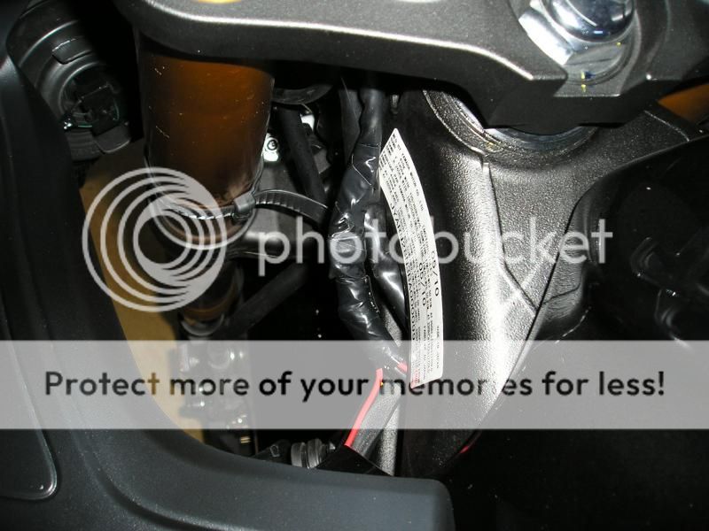
Here's a pic of my finished & taped connection. The red wire going in & out is the new low beam lead from the right headlight. I taped it in here to keep things as tidy as possible. The black lead is the one that's tapped into the low beam wire on the switch.
Step 3: Running the wires to the battery box area
This is easier if you remove the fuel tank. You might be able to do it by propping up the tank, but I didn't have much luck when I tried it. If you choose to remove the tank, I'm not going to go through that process. It can be found in other threads or on Youtube.
- Remove both seats
- Remove both inner plastic trim panels (you already removed the left one in step 2)
- Remove the tank shroud
- Remove the tank
- Optional: If you are so inclined, you can remove the airbox too. Up to you. I didn't because it is a PITA and you don't really need to remove it to run the wires. If you do, you can run them all the way along the factory looms, but you don't HAVE to.
- Feed the new wires from the headlight & the low beam switch into the frame & fish them out near the front of the airbox. It takes some patience & nimble fingers help. Pull the wires through leaving them hanging next to the airbox on the left side.
- Feed the wires back to the battery box area. There's a bunch of open space in front of the battery above the coil mounting bracket. Lots of room to maneuver.
- Cut a length of the loom material and cover the new wires, taping the ends of the loom. NOTE: Don't extend the loom all the way into the battery box area - maybe 2 or three inches depending on where you plan to mount the relay. Give yourself room to work.
- Stuff the loom under the foam pad around the airbox on the left side. Should be no problem to do that.
- Unfortunately, I don't have a picture of this. I'd have to remove the tank again and I really don't want to do that. A later pic will show where the leads come out.
Step 4: Prepare the battery power lead
- Cut a short piece of 16AWG wire (red ideally) for your power lead - 3 or 4 inches.
- Crimp and/or solder a 1/4" ring terminal to one end (this will be attached to your batter positive terminal later)
- join the other end to one end of your inline fuse. I would recommend splicing & soldering this connection, and cover it with heat shrink.
- leave the other end of the fuse for now.
- I don't have a picture of this either. You will be able to see in the later pic, enough to get the idea.
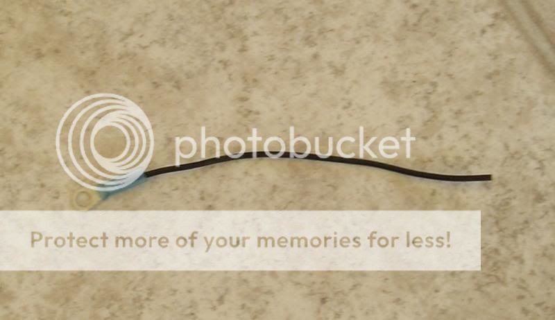
Step 5: Prepare your ground wire
- Cut a length of 16AWG wire (black ideally) - say 6 inches or so
- Crimp and/or solder a 1/4" ring terminal to one end (to be attached to a ground point later)
- Leave the other end for now
- It will look something like this
Step 6: Decide where & how to mount your relay
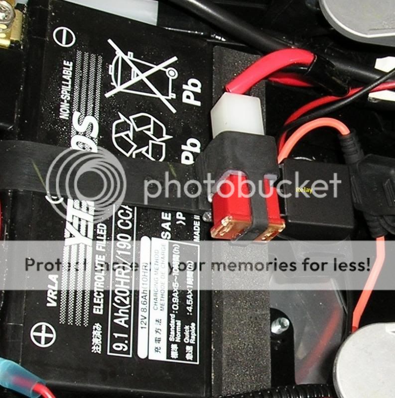
Not much to say here. There are a number of options - mount to an existing bolt, fab a bracket, whatever you want really. I had a rubber strap from an unused flasher relay, so I slipped it under the battery strap & mounted the relay to the front of the battery box. Here's a pic.
Step 7: Run wires & trim, add connectors, make relay connections
- NOTE: Do not connect your battery & ground wires at this time
- run your battery & ground wires to the relay location, keeping things as tidy as you can. Trim to length.
- Crimp and/or solder a .250" female spade plug to the end of each of these 4 new wires.
- plug the wires into your relay for the power, ground and right low beam as shown in the diagram above
- Do not connect the trigger wire from the high/low beam switch at this time. We'll test the circuit first.
Step 8: Battery & ground connections and circuit test
- Connect the ring terminal of your new ground lead to a chassis ground. There's one under the tank near the airbox on the right side.
- Disconnect your battery ground lead. Push it aside & make sure it is secure & can't touch the battery terminal.
- Disconnect your battery positive lead, and reconnect with your new power lead to your relay
- Reconnect your battery ground lead
- Install a fuse in your in-line fuse holder
- Cut a length of 16 AWG wire, long enough to reach from your relay to the positive terminal of your battery. Strip both ends. You can attach a .250" female spade connector to one end if you have an extra one
- Connect one end to the trigger terminal on your relay (where the wire from the high/low beam switch would normally go). If you used a spade terminal, plug that in to the relay.
- carefully touch the other end to your positive battery terminal. If you've wired everything correctly, your right low beam should turn on!
- If your right low beam turned on, you're good to go on to the next step. If not, re-check your wiring & all connections and try again.
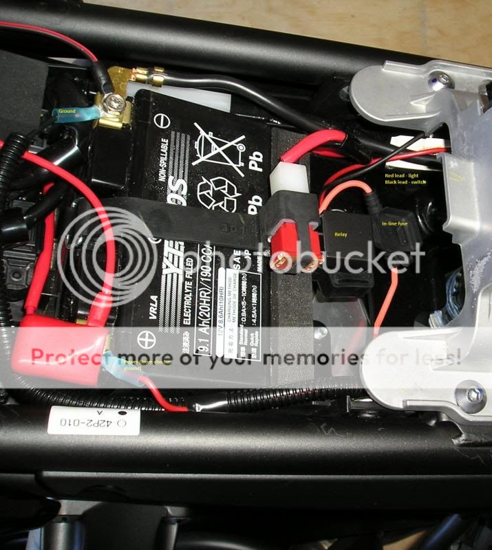
Here's how mine looks. I do have to tidy up the wiring, but I wanted to leave things somewhat open so you could see how I ran the wires. I plan on changing this around for a more tidy install, so this is just for illustration.
Step 9: Tidying up & partial bike reassembly
- Disconnect your test lead from the relay and plug in your high/low beam switch tap lead
- Tape the connection where you tapped into the factory loom for the high/low beam switch (the green wire tap-in)
- install & tape wiring loom to protect new wires where necessary
- zip-tie or tape any "loose" wires
- Reinstall the airbox, tank & trim (whatever you had removed)
Step 10: Final test
- Once you have reinstalled the tank & trim, grab a pair of sunglasses. Put them on
- Move the high/low beam switch to the low beam position
- Start the bike. Both headlights should be on
- Look at the right headlight from the side and switch to high beam. You should be able to see the low beam filament (top one I think) in the bulb shut off, and the high beam filament (bottom) turn on. If that happens, you're done!
Here's a pic of the end result. Looks much better, better visibility at night, and you're easier to see as well.

Kirb
Hi all,
When I mentioned I had done this mod a few days ago a number of people asked for a write-up on how I did it. I'll start with a basic how-to and add details & pics as I find time. Yamaha made this an easy mod by fitting the Fazer with a dual-filament bulb & reflector on the high beam side. They just didn't bother wiring in the additional low beam.
If you recall, another forumite (Fazed) also posted a how-to for this mod. He took a very direct approach, and a very simple one, but as I had noted in his thread I had concerns about the load on the factory wiring. He had said he was told the low beam wire he utilized for 12V power (running through the hi-lo beam switch) was not used in the Fazer8, but with no proof of that and a bit of a background in my hobby of building tube amplifiers I still felt there was a better, and safer, way to approach it. I also don't like running a lot of current through a switch if it is avoidable. So here we go.
I know that looks like a lot, but I'm a systems analyst by trade so detail is kinda my thing. This really isn't a difficult mod - just be careful & meticulous and you should be just fine. If you don't feel 100% comfortable doing this modification, get a professional or a competent friend to do it.
I don't claim this is the best way to do this, and certainly not the simplest, but I feel it's a safe approach that isolates the new circuit from the factory wiring.
First, the parts list. Where applicable, the part# I used is in parenthesis. I got all of the stuff at Canadian Tire.
- In-line fuse - weatherproof (Littelfuse FHAC2BP/FHAC0002XP)
- SPST automotive headlight relay (Pilot PL-RY2CT)
- 1 x .250" female spade connector (for right headlight plug, low beam filament)
- 4 x .250" female spade connector OR SPST relay socket (for connections to relay)
- 2 x 1/4" ring terminals (weatherproof) (battery/ground connections) (Motomaster 20-6982-8)
- approx 12' 16 AWG wire (your choice of colors - I had red & black on hand).
- 1 t-tap for 16AWG wire (or splice/solder if you prefer)
- 1 10A fuse (current draw is 5-6 amps)
- A few feet of 1/4" automotive wiring loom flex tubing. (Certified 020-7502-6)
Here's a wiring diagram for the circuit with the relay. Pretty straight forward really.

Some of you probably have the know-how to take things from there. When I get some time I'll post some more details & pics on how I implemented this. There are many ways to go about it. I took an approach where I didn't have to disassemble the whole freakin' bike and still kept things tidy.
*** PLEASE NOTE *** When I talk about the right side headlight in the descriptions below, I and referring to the right side when sitting on the bike. Facing the bike it is the LEFT headlight.
Here's how I did it...
Step 1: Add low beam wire to factory right headlight plug
- Unplug the right headlight plug
- Use a small screwdriver to release the back of the plug. You should see a vacant slot at the top of the plug. You will be inserting a .250" female spade connector in there...but not just yet!
- test fit your spade connector on the headlight bulb. It should be snug. .250" is a little too narrow really, and I had to open mine up a touch. If you can find the correct spade connector or have an old H4 connector kicking around that you can cannibalize that would be ideal. I had neither.
- Once you have your spade connector fitting the bulb, remove it and crimp or solder on a length of 16 AWG wire. Cut a 6' length for now. You can trim it to fit later. If your spade connector has a plastic cover, remove it.
- Insert the new wire into the vacant slot in the headlight plug. Route the wire at right angles to the plug in the available channel, and snap the back on the plug.
- Test-fit the plug to the headlight bulb. If everything fits OK, move on. If not, mess with the fit until you are comfortable with it.
- Tape the new wire to the last couple of inches of the factory wires/loom for the right headlight.
- Run the new wire along side the factory loom along the bottom edge of the cowling and around to the left side. Tape it & zip tie it to the original loom along the way where possible.
- Optional You could disassemble the upper cowl to get at the factory loom and tape the new wire in in the whole way along. Up to you. IMO it isn't worth the trouble. If the new wire is behind the cowl with the loom & secured it should not be a problem. It will be out of the weather & should be well protected.
Here's a pic of the modified plug. The red wire is the new low beam lead.

Step 2: Splice into the existing low beam (green) wire from the hi/lo beam switch
You have to decide where you want to splice/t-tap into this loom. I decided to do it just before the loom runs into the frame on the left hand side. It is fairly well hidden hidden & out of the weather, and didn't require pulling the tank & airbox.
- remove the left black trim panel (the one on the inside of the fairing)
- Locate the black loom coming from the left handlebar switch pod. It will be the loom going into the top of the pod
- follow the loom down to the frame. Move back a couple inches & carefully cut a slit in the loom, about 1 inch or so.
- Fish the green wire out of the loom
- cut a length of 16AWG wire (3 or 4 feet will be plenty)
- using a t-tap, splice into the green wire
- NOTE: If you prefer, you can solder this connection or use whatever your preferred method of splicing is. IMO the t-tap should suffice here as this is a low-current trigger for the relay only, not the hot wire for the actual light.
- Don't tape the connection just yet. We'll want to test it first.
Here's a pic of my finished & taped connection. The red wire going in & out is the new low beam lead from the right headlight. I taped it in here to keep things as tidy as possible. The black lead is the one that's tapped into the low beam wire on the switch.

Step 3: Running the wires to the battery box area
This is easier if you remove the fuel tank. You might be able to do it by propping up the tank, but I didn't have much luck when I tried it. If you choose to remove the tank, I'm not going to go through that process. It can be found in other threads or on Youtube.
- Remove both seats
- Remove both inner plastic trim panels (you already removed the left one in step 2)
- Remove the tank shroud
- Remove the tank
- Optional: If you are so inclined, you can remove the airbox too. Up to you. I didn't because it is a PITA and you don't really need to remove it to run the wires. If you do, you can run them all the way along the factory looms, but you don't HAVE to.
- Feed the new wires from the headlight & the low beam switch into the frame & fish them out near the front of the airbox. It takes some patience & nimble fingers help. Pull the wires through leaving them hanging next to the airbox on the left side.
- Feed the wires back to the battery box area. There's a bunch of open space in front of the battery above the coil mounting bracket. Lots of room to maneuver.
- Cut a length of the loom material and cover the new wires, taping the ends of the loom. NOTE: Don't extend the loom all the way into the battery box area - maybe 2 or three inches depending on where you plan to mount the relay. Give yourself room to work.
- Stuff the loom under the foam pad around the airbox on the left side. Should be no problem to do that.
- Unfortunately, I don't have a picture of this. I'd have to remove the tank again and I really don't want to do that. A later pic will show where the leads come out.
Step 4: Prepare the battery power lead
- Cut a short piece of 16AWG wire (red ideally) for your power lead - 3 or 4 inches.
- Crimp and/or solder a 1/4" ring terminal to one end (this will be attached to your batter positive terminal later)
- join the other end to one end of your inline fuse. I would recommend splicing & soldering this connection, and cover it with heat shrink.
- leave the other end of the fuse for now.
- I don't have a picture of this either. You will be able to see in the later pic, enough to get the idea.
Step 5: Prepare your ground wire
- Cut a length of 16AWG wire (black ideally) - say 6 inches or so
- Crimp and/or solder a 1/4" ring terminal to one end (to be attached to a ground point later)
- Leave the other end for now
- It will look something like this

Step 6: Decide where & how to mount your relay
Not much to say here. There are a number of options - mount to an existing bolt, fab a bracket, whatever you want really. I had a rubber strap from an unused flasher relay, so I slipped it under the battery strap & mounted the relay to the front of the battery box. Here's a pic.

Step 7: Run wires & trim, add connectors, make relay connections
- NOTE: Do not connect your battery & ground wires at this time
- run your battery & ground wires to the relay location, keeping things as tidy as you can. Trim to length.
- Crimp and/or solder a .250" female spade plug to the end of each of these 4 new wires.
- plug the wires into your relay for the power, ground and right low beam as shown in the diagram above
- Do not connect the trigger wire from the high/low beam switch at this time. We'll test the circuit first.
Step 8: Battery & ground connections and circuit test
- Connect the ring terminal of your new ground lead to a chassis ground. There's one under the tank near the airbox on the right side.
- Disconnect your battery ground lead. Push it aside & make sure it is secure & can't touch the battery terminal.
- Disconnect your battery positive lead, and reconnect with your new power lead to your relay
- Reconnect your battery ground lead
- Install a fuse in your in-line fuse holder
- Cut a length of 16 AWG wire, long enough to reach from your relay to the positive terminal of your battery. Strip both ends. You can attach a .250" female spade connector to one end if you have an extra one
- Connect one end to the trigger terminal on your relay (where the wire from the high/low beam switch would normally go). If you used a spade terminal, plug that in to the relay.
- carefully touch the other end to your positive battery terminal. If you've wired everything correctly, your right low beam should turn on!
- If your right low beam turned on, you're good to go on to the next step. If not, re-check your wiring & all connections and try again.
Here's how mine looks. I do have to tidy up the wiring, but I wanted to leave things somewhat open so you could see how I ran the wires. I plan on changing this around for a more tidy install, so this is just for illustration.

Step 9: Tidying up & partial bike reassembly
- Disconnect your test lead from the relay and plug in your high/low beam switch tap lead
- Tape the connection where you tapped into the factory loom for the high/low beam switch (the green wire tap-in)
- install & tape wiring loom to protect new wires where necessary
- zip-tie or tape any "loose" wires
- Reinstall the airbox, tank & trim (whatever you had removed)
Step 10: Final test
- Once you have reinstalled the tank & trim, grab a pair of sunglasses. Put them on
- Move the high/low beam switch to the low beam position
- Start the bike. Both headlights should be on
- Look at the right headlight from the side and switch to high beam. You should be able to see the low beam filament (top one I think) in the bulb shut off, and the high beam filament (bottom) turn on. If that happens, you're done!
Here's a pic of the end result. Looks much better, better visibility at night, and you're easier to see as well.

Kirb
Last edited:
")