
AlCab
New member
I recently had Brian Harris at Motydesign.com in Salt Lake City, UT integrate an Acumen DG8 gear indicator (GI) into the gauge cluster of my FZ8. This covers how to wire the DG8 GI into your bike’s wiring harness. This would also apply if you choose to just mount the GI externally instead of having it integrated.
First, we have to remove the gauge cluster and ship it to Brian for him to do his magic. Here are the steps:
1. Remove the small windscreen above the headlight by removing the two screws then sliding the windscreen down to release the tabs in the front.
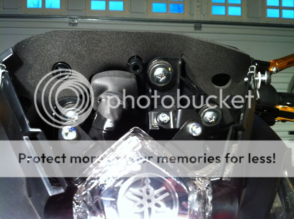
2. Below is what you see after you remove the windscreen. You can do this a couple of ways but I found the easiest way is to remove the gauge pod with the gauge pod bracket attached. In the pic below, remove the single small Phillips head screw at about the middle of the gauge cluster that holds the gauge bracket to the headlight bracket.
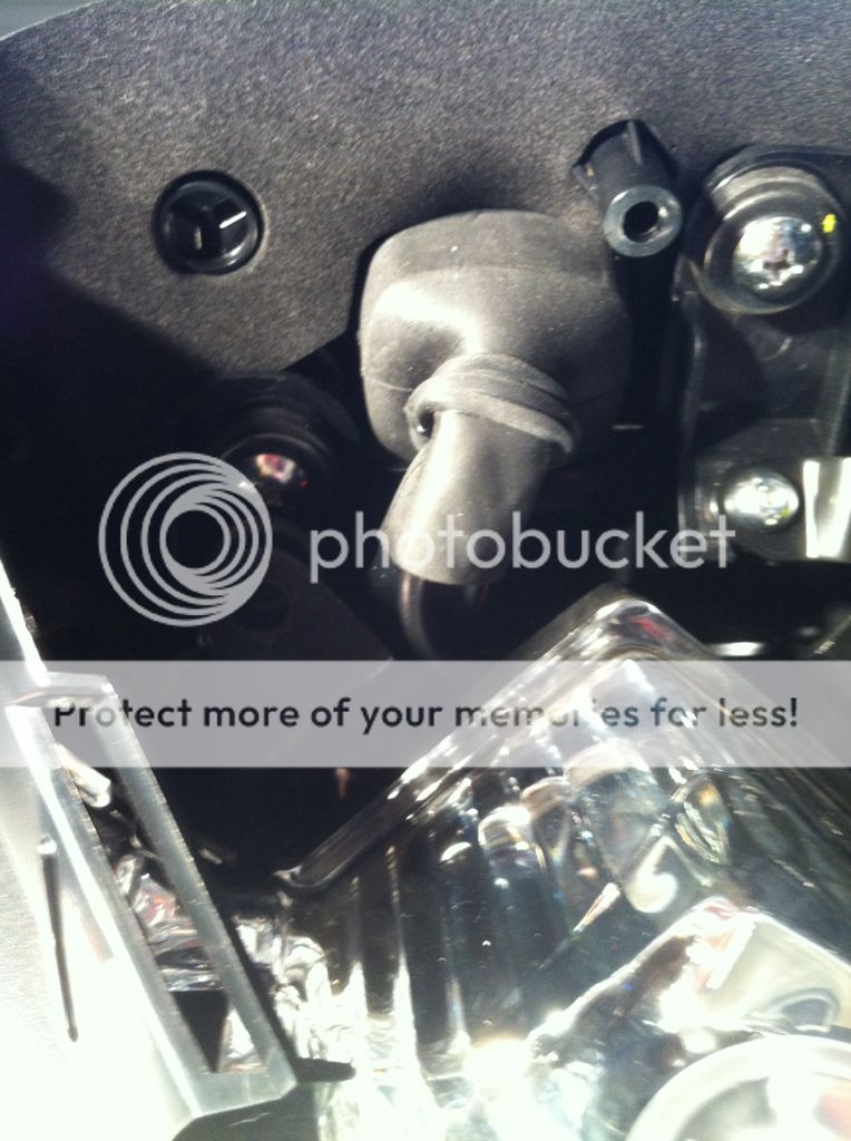
3. Next, pull back the rubber boot and disconnect the connector at back of gauge cluster. Note that there is a tab on the bottom side of the connector that you need to push in order to remove the connector.
4. Now go to the front of the gauge pod and remove the two allen head bolts near the handlebars that hold the gauge pod bracket to the top fork clamp. Now carefully remove the gauge pod and bracket. Below is what it looks like after you remove it (the integrated GI is already installed in this pic).

Now separate the gauge pod from the bracket and send it off to Brian. Note that you will lose the trip odometer readings but your total odometer reading will remain intact. He charges $210 to integrated the GI into your gauge pod and that includes the cost of the GI. The GI by itself is about $125 shipped so I think $85 is fair price for the integration work. Brian normally turns it around in about a week.
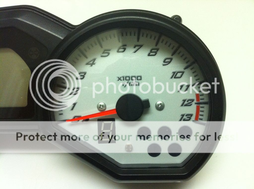
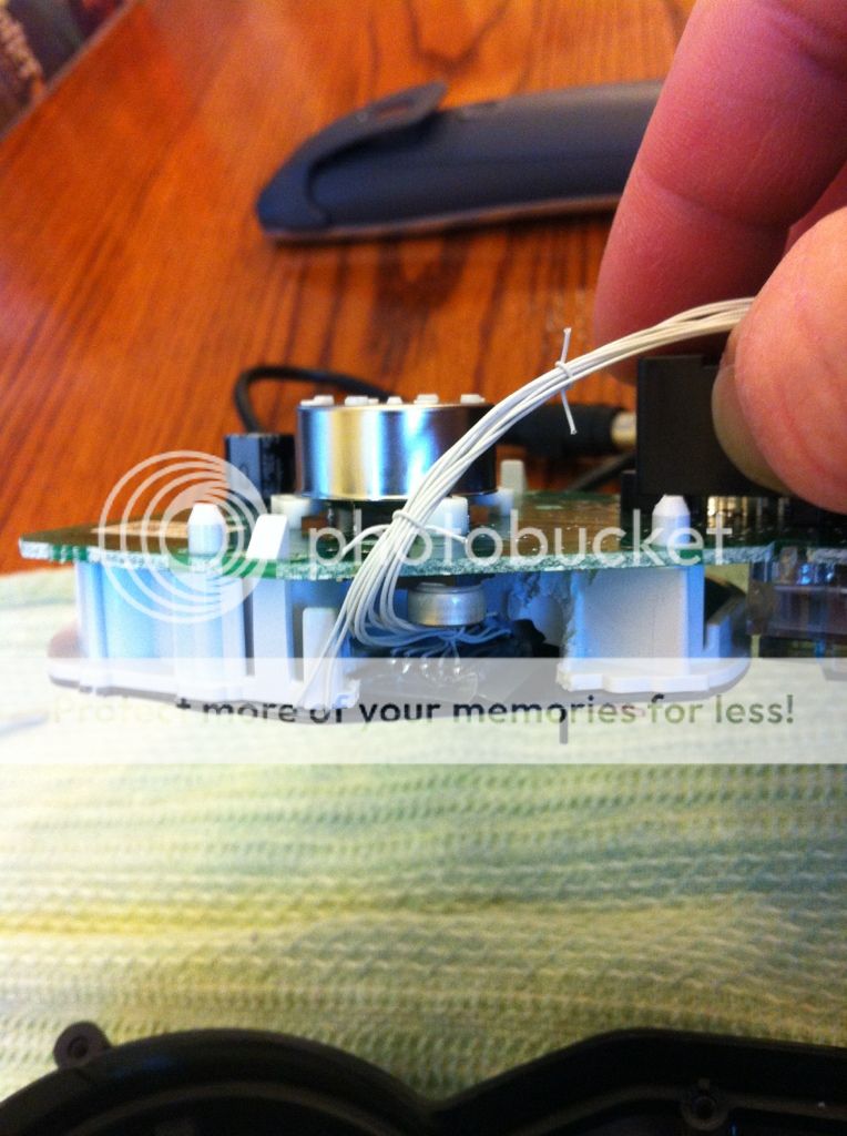
Here is what it looks like when you get it back.
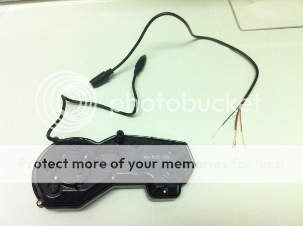
The wires running to the gauge pod back cover is for the programming button.
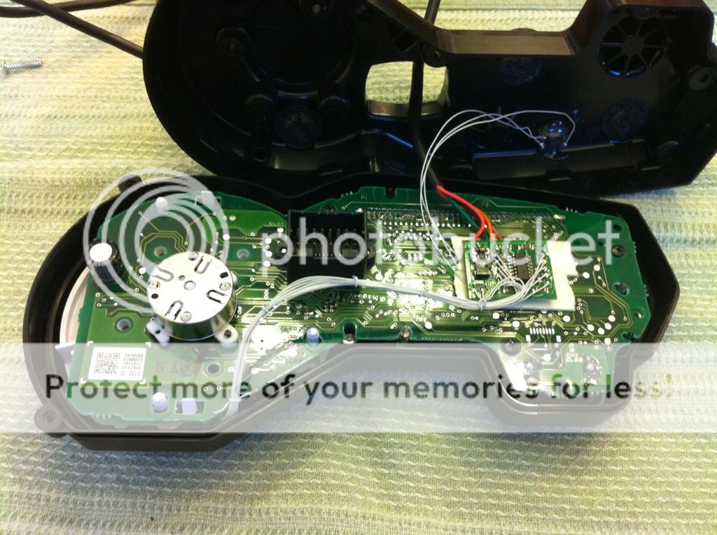

You can see that Brian has to cut out some of the plastic behind the gauge face to make room for the GI display.
Once you get it back, reinstall the gauge pod and bracket but leave the windscreen off as you need access to the programming button on the back of the gauge pod when you program the DG8 to learn your gears. Note that you will need to feed the GI connector through the rubber connector boot. It’s a tight fit but it can be done.

Now you will need to connect 5 wires from the DG8’s pigtail to your bike’s wiring harness. Here are the steps:
1. Disconnect the battery to make sure you don’t accidentally short anything out.
2. Siphon gas from tank and remove gas tank to give yourself plenty of room to work. It only takes 5 minutes to remove the tank so there is no reason not to remove it. Then remove the airbox.
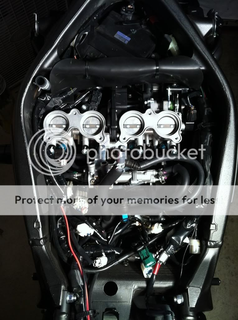
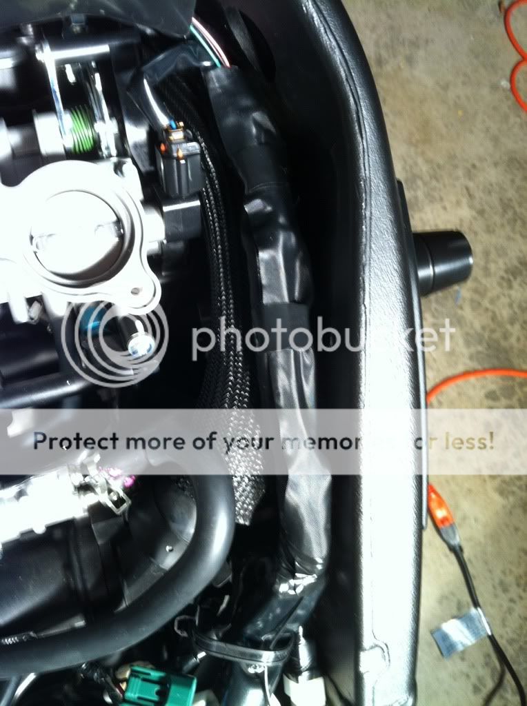
So this is what it looks like with the gas tank and airbox removed.
These are the two wire looms on the left side of the bike that you will need to access. They connect to the ECU via two connectors – one large, and one small. Look at the ECU to determine which wire loom leads to which connector. On my bike the large wire loom was on top of the small wire loom. You will need one wire from each loom.
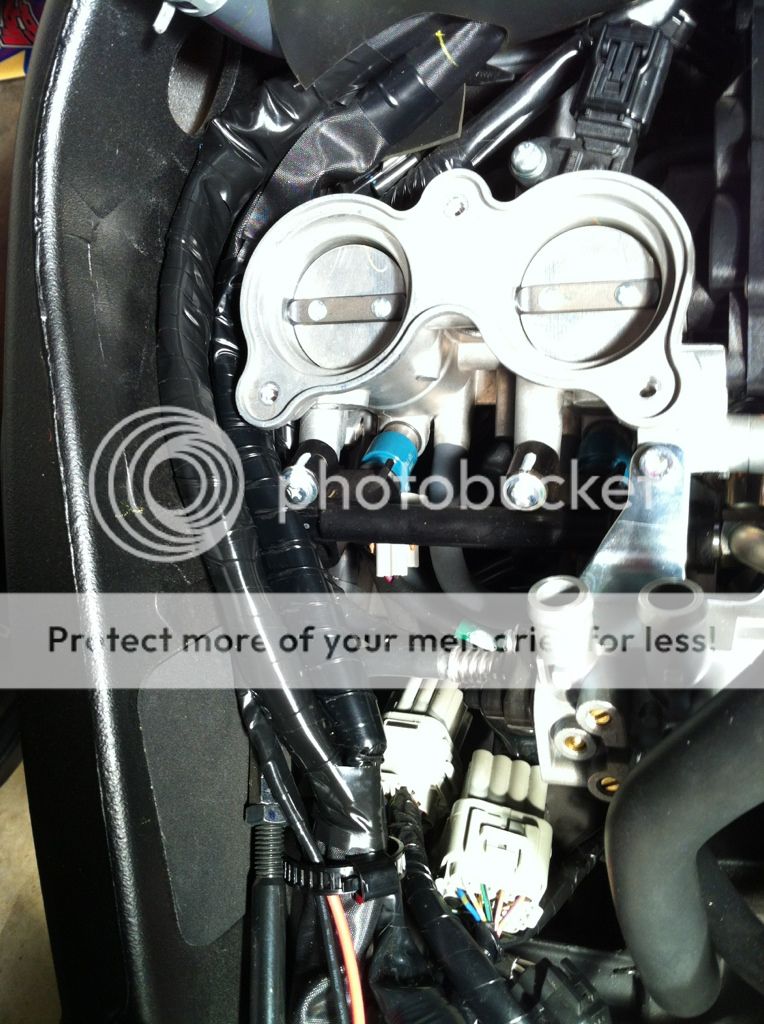
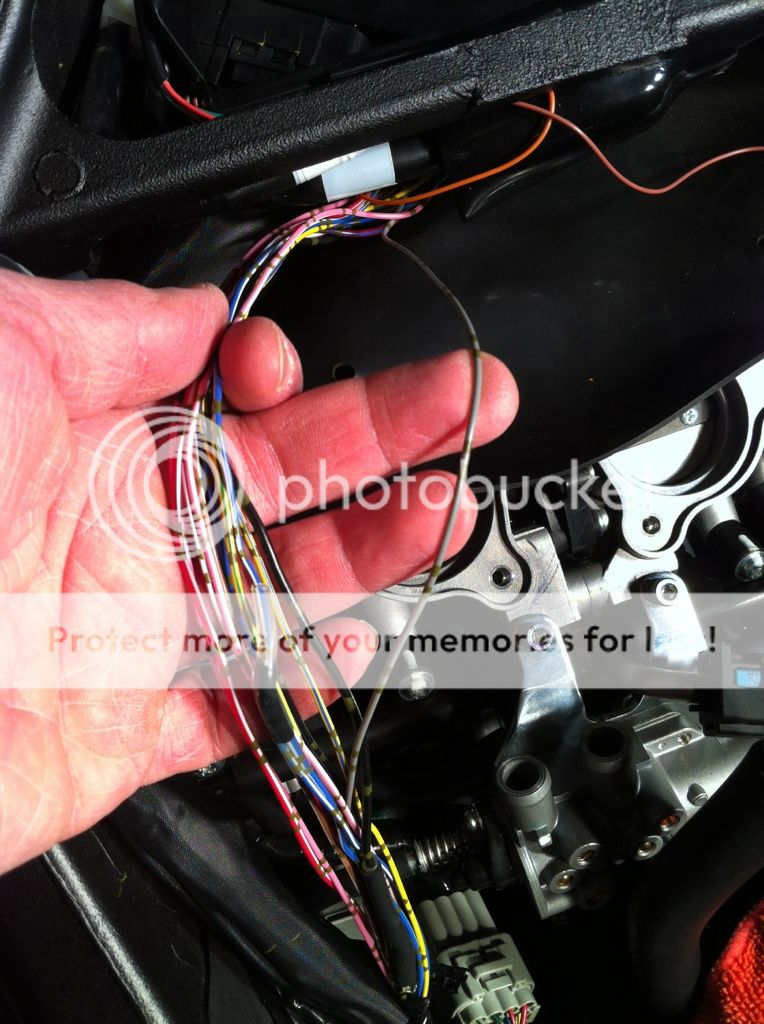
Let’s start with the small wire loom. The looms are zip tied to the inside of the frame. Release (do not cut) the zip ties and remove them to reuse later. Unwrap or cut the black electrical tape to expose the wire loom then peel open the loom (do not cut it) so you can reuse it later. It is stuck together with adhesive so just peel it open, remove it, then stick it back together and set it aside. Find the solid gray wire as shown in the pic below. This is the crankshaft position sensor wire. You will need to connect the brown wire from the DG8 to this wire.
Carefully strip about 1-1/2” of insulation from the gray wire (do NOT cut the wire). I used a utility knife with a brand new blade and carefully cut around the insulation about 1-1/2” apart then slit the insulation down the middle. Next, strip about 2” of insulation from the end of the brown DG8 wire. Now wrap the exposed DG8 wire tightly around the exposed section of the FZ8 gray wire. Now solder the wires together. A 25W soldering iron from Home Depot works great. Do not over heat the wires so you don’t melt the insulation. Get the wire just hot enough, melt some solder on it, then remove the iron. Should only take a few seconds. Don’t overdo it! If you have not done much/any soldering, I highly recommend that you watch some how to videos on youtube. It helped me a lot. Now wrap the soldered connection with electrical tape and then reinstall the wire loom and wrap it with electrical tape.
Soldering tip: Heat the wire from the bottom and apply the solder on the wire from the top. Do not touch the solder to the soldering iron or you will make a mess.
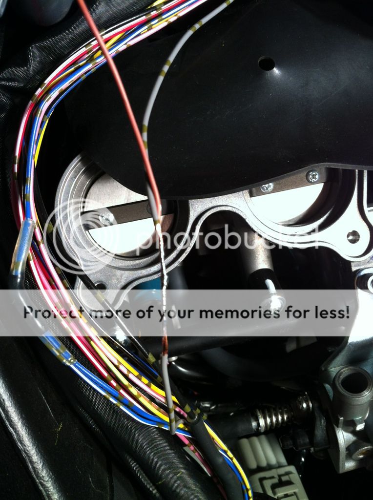
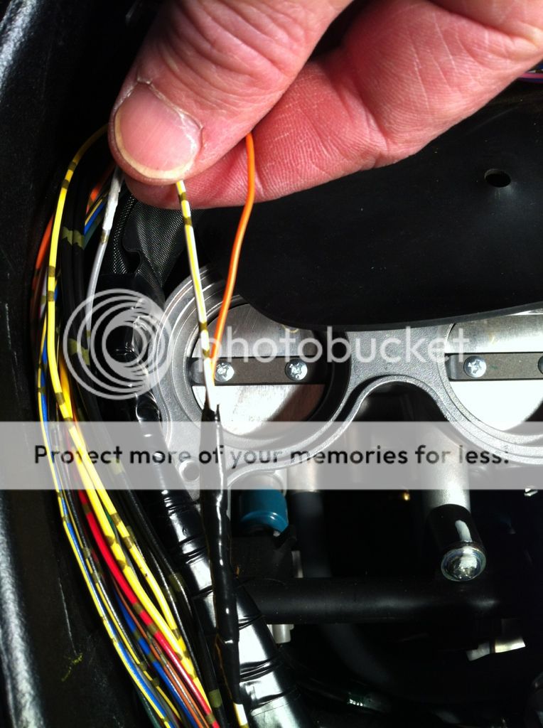
Now let’s move on to the large ECU wire loom. Open up this loom and find the white wire with a yellow stripe. This is the speed sensor wire. You will need to connect the orange DG8 wire to this wire. See finished pic below. Now reinstall the loom.
WARNING: There is also a solid gray wire in the large loom as you can see below. This is NOT the crankshaft position sensor wire so do NOT connect the brown DG8 wire to this gray wire. I made that mistake and it does not work. You HAVE to connect the brown DG8 wire to the gray wire in the SMALL loom.
Now let’s move on to the wire loom on the right side of the bike.
We will need to connect to two wires from this loom as follows:
Switched Power – connect the DG8 red wire to FZ8 red wire with white stripe
Neutral Switch – connect DG8 green wire to FZ8 light blue wire with white stripe
Note that there are several shades of blue wires in this bundle – make sure you choose the LIGHT blue with white stripe. Also, there are several red wires with white stripes – I chose one of the larger ones.
Connect them the same way as you did the others. On my bike, the wires on this loom were all intertwined together so it was harder to isolate and work on the wires you need. It’s not impossible, just a little harder.
Note that in the pic below, you can see the black wire which is soldered to another black wire. I extended the DG8 black wire so it would reach the battery so that is what you are seeing here.
Almost done, we have one wire left to connect. Connect the DG8 black wire directly to the negative terminal on the battery. You could also solder it to one of the solid black wires in any of the looms but running it straight to the battery is easier.
All done. Now put everything back together and follow the programming instructions in the manual at the link below:
http://www.riderstation.com/DG8_Instr_Feb_03.pdf
Warning: It should take less than 30 seconds for the DG8 to learn first gear. If it does not do it in that time, you probably wired something wrong.
Other programming tips: Contrary to what the instructions say, start the bike up and let it idle in neutral before starting the learning process. Also, run the bike between 2k and 4k rpm when teaching the DG8 the gears. You don't need anymore rpms than that.
Here is a pic of the completed install.
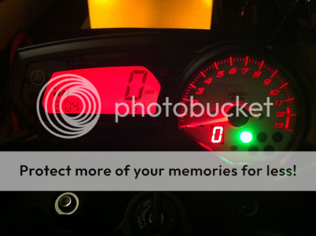
Here is a video of the DG8 GI in action.
Acumen DG8 Gear Indicator - YouTube
All in all, this is not a complicated install. Just take your time and follow the instructions above and you will be fine. I hope that this inspires you to install a GI on your FZ8") It's a great mod and Brian does a great job with the integration.
It's a great mod and Brian does a great job with the integration.
First, we have to remove the gauge cluster and ship it to Brian for him to do his magic. Here are the steps:
1. Remove the small windscreen above the headlight by removing the two screws then sliding the windscreen down to release the tabs in the front.
2. Below is what you see after you remove the windscreen. You can do this a couple of ways but I found the easiest way is to remove the gauge pod with the gauge pod bracket attached. In the pic below, remove the single small Phillips head screw at about the middle of the gauge cluster that holds the gauge bracket to the headlight bracket.
3. Next, pull back the rubber boot and disconnect the connector at back of gauge cluster. Note that there is a tab on the bottom side of the connector that you need to push in order to remove the connector.
4. Now go to the front of the gauge pod and remove the two allen head bolts near the handlebars that hold the gauge pod bracket to the top fork clamp. Now carefully remove the gauge pod and bracket. Below is what it looks like after you remove it (the integrated GI is already installed in this pic).
Now separate the gauge pod from the bracket and send it off to Brian. Note that you will lose the trip odometer readings but your total odometer reading will remain intact. He charges $210 to integrated the GI into your gauge pod and that includes the cost of the GI. The GI by itself is about $125 shipped so I think $85 is fair price for the integration work. Brian normally turns it around in about a week.
Here is what it looks like when you get it back.
The wires running to the gauge pod back cover is for the programming button.
You can see that Brian has to cut out some of the plastic behind the gauge face to make room for the GI display.
Once you get it back, reinstall the gauge pod and bracket but leave the windscreen off as you need access to the programming button on the back of the gauge pod when you program the DG8 to learn your gears. Note that you will need to feed the GI connector through the rubber connector boot. It’s a tight fit but it can be done.
Now you will need to connect 5 wires from the DG8’s pigtail to your bike’s wiring harness. Here are the steps:
1. Disconnect the battery to make sure you don’t accidentally short anything out.
2. Siphon gas from tank and remove gas tank to give yourself plenty of room to work. It only takes 5 minutes to remove the tank so there is no reason not to remove it. Then remove the airbox.
So this is what it looks like with the gas tank and airbox removed.
These are the two wire looms on the left side of the bike that you will need to access. They connect to the ECU via two connectors – one large, and one small. Look at the ECU to determine which wire loom leads to which connector. On my bike the large wire loom was on top of the small wire loom. You will need one wire from each loom.
Let’s start with the small wire loom. The looms are zip tied to the inside of the frame. Release (do not cut) the zip ties and remove them to reuse later. Unwrap or cut the black electrical tape to expose the wire loom then peel open the loom (do not cut it) so you can reuse it later. It is stuck together with adhesive so just peel it open, remove it, then stick it back together and set it aside. Find the solid gray wire as shown in the pic below. This is the crankshaft position sensor wire. You will need to connect the brown wire from the DG8 to this wire.
Carefully strip about 1-1/2” of insulation from the gray wire (do NOT cut the wire). I used a utility knife with a brand new blade and carefully cut around the insulation about 1-1/2” apart then slit the insulation down the middle. Next, strip about 2” of insulation from the end of the brown DG8 wire. Now wrap the exposed DG8 wire tightly around the exposed section of the FZ8 gray wire. Now solder the wires together. A 25W soldering iron from Home Depot works great. Do not over heat the wires so you don’t melt the insulation. Get the wire just hot enough, melt some solder on it, then remove the iron. Should only take a few seconds. Don’t overdo it! If you have not done much/any soldering, I highly recommend that you watch some how to videos on youtube. It helped me a lot. Now wrap the soldered connection with electrical tape and then reinstall the wire loom and wrap it with electrical tape.
Soldering tip: Heat the wire from the bottom and apply the solder on the wire from the top. Do not touch the solder to the soldering iron or you will make a mess.
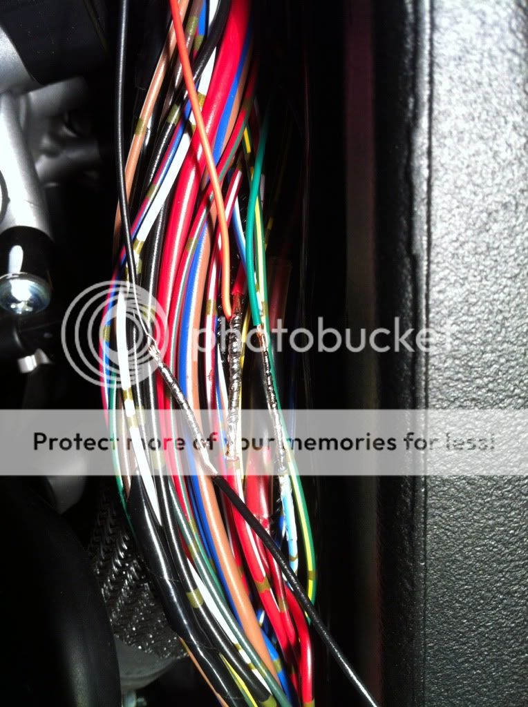
Now let’s move on to the large ECU wire loom. Open up this loom and find the white wire with a yellow stripe. This is the speed sensor wire. You will need to connect the orange DG8 wire to this wire. See finished pic below. Now reinstall the loom.
WARNING: There is also a solid gray wire in the large loom as you can see below. This is NOT the crankshaft position sensor wire so do NOT connect the brown DG8 wire to this gray wire. I made that mistake and it does not work. You HAVE to connect the brown DG8 wire to the gray wire in the SMALL loom.
Now let’s move on to the wire loom on the right side of the bike.
We will need to connect to two wires from this loom as follows:
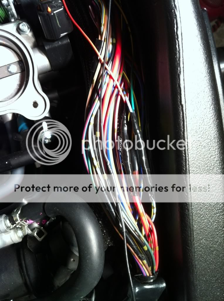
Switched Power – connect the DG8 red wire to FZ8 red wire with white stripe
Neutral Switch – connect DG8 green wire to FZ8 light blue wire with white stripe
Note that there are several shades of blue wires in this bundle – make sure you choose the LIGHT blue with white stripe. Also, there are several red wires with white stripes – I chose one of the larger ones.
Connect them the same way as you did the others. On my bike, the wires on this loom were all intertwined together so it was harder to isolate and work on the wires you need. It’s not impossible, just a little harder.
Note that in the pic below, you can see the black wire which is soldered to another black wire. I extended the DG8 black wire so it would reach the battery so that is what you are seeing here.
Almost done, we have one wire left to connect. Connect the DG8 black wire directly to the negative terminal on the battery. You could also solder it to one of the solid black wires in any of the looms but running it straight to the battery is easier.
All done. Now put everything back together and follow the programming instructions in the manual at the link below:
http://www.riderstation.com/DG8_Instr_Feb_03.pdf
Warning: It should take less than 30 seconds for the DG8 to learn first gear. If it does not do it in that time, you probably wired something wrong.
Other programming tips: Contrary to what the instructions say, start the bike up and let it idle in neutral before starting the learning process. Also, run the bike between 2k and 4k rpm when teaching the DG8 the gears. You don't need anymore rpms than that.
Here is a pic of the completed install.
Here is a video of the DG8 GI in action.
Acumen DG8 Gear Indicator - YouTube
All in all, this is not a complicated install. Just take your time and follow the instructions above and you will be fine. I hope that this inspires you to install a GI on your FZ8
It's a great mod and Brian does a great job with the integration.
Last edited:
 . This kind of detail is invaluable to anyone looking to tackle this project.
